Acrylic Pendulum Clock
March 22, 2015
I designed and built a pendulum clock, from acrylic parts cut by a laser cutter. Here's a video of it in action:
The parts are all cut from paths generated by a Python program. The program generates a JSON file with all the part data. This file can both be used to cut parts (by converting them to SVG files that the laser cutter can use) or to visualize the clock in 3D:
Use the mouse to orbit around the clock and the scroll wheel to zoom in and out. In the full-page view you can also hold down the Space key and use the mouse to pan around, as well as press 1, 2, or 3 to go real time, 60 times faster, and 12*60 times faster, respectively.
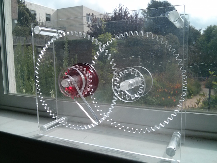
The large pink gear (in the upper-right) is the second hand; the large white gear is the minute hand; the large green gear is the hour hand. The weight is wound around the fourth axle from the left (large cyan gear). To the right is the escapement mechanism and pendulum.
There were many restrictions on the set of gears and their sizes. For example, I wanted the hour and minute hand to be on the same axle, which meant that I needed two pairs of gears that satisfied two requirements: The sum of their teeth had to be the same, and the product of their ratios had to equal 12. The pairs 64/16 and 60/20 worked perfectly.
I was having a hard time multiplying by 60 (to go from the second hand to the minute hand) because the factors of 60 are 2, 2, 3, and 5, and it's hard to get a ratio of 5 between two gears. I eventually realized that I could inject numbers into the ratios that canceled out, so I wasn't stuck using only the factors of the original number or stuck using pairs that had simple ratios. I ended up with 60/20, 49/20, 60/21, and 60/21. There are four sevens in there that cancel out completely but keep the gears within a reasonable range (about 16 to 64 teeth).
My initial design for the escapement wheel was the stereotypical spiked-wheel:

This didn't work in acrylic because the points are too thin and they melt. I changed my design to one inspired by a clock made by Michael Birken. It's more wasteful of energy but works fine.
I had initially wanted the whole clock to be acrylic. I used acrylic rods for the axles and fishing wire for holding up the weight. I built a prototype this way:
The all-acrylic idea had severe drawbacks. One was that acrylic rods, at least the kind I could buy at Tap Plastics, were slightly oval, not round. Glueing the gears to the rods was difficult and in practice often marred the gear when the glue ran. (The running glue also sometimes glued pieces together that weren't supposed to be.) The worst problem was that glued pieces cannot be re-used, meaning that if I made any kind of mistake, I had to trash every part and build it all again.
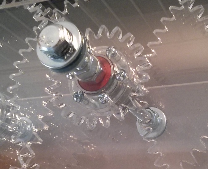
I switched to a fixed-axle system, using bolts. (I say “fixed-axle” because with the acrylic rods, they turned with the gears. The bolts are attached to the frame and the gears spin around them.) Each gear has a skateboard ball bearing at its center, which not only turns much better than acrylic-on-acrylic, but looks cool because the bearings are a deep color red. The bearings dictated the size of the axle bolts: 5/16".
I now had to find a way to keep pairs of gears turning together, something I did with smaller bolts. Each pair of gears has six #6-32 bolts holding them together. Between the gears are acrylic separators that both keep the gears apart and provide something for the ball bearings to push against. This picture shows both the binding bolts and the red bearings. The smaller gear is in front, followed by two quarter-inch separators, followed by the larger gear:
Tooth design
The first few (and funnest!) months of the project were spent
deriving the math for the shape of the gear teeth. This is in the
gear.py file. The traditional cartoon shape of a tooth
(usually square) performs poorly because as the two teeth from the
different gears touch, their point of contact moves. This causes
the driven gear to change speeds, since the ratio of the effective
circles changes.
The solution is to shape the tooth such that it “pulls back” from the other one. The contact point still moves, but the teeth pull away from each other perfectly to make up for it.
In the following diagram, the colors represent the different parts of each tooth. The blue section on top and red section on bottom follow circles around the center of the gear. Peeling off the red root are two yellow arcs of circles. These are fillets. They're not necessary for the proper functioning of the tooth, but they make the gear structurally stronger. Without them, the green and red parts would meet at sharp angles, which are weak and can break under stress. It's important that the fillet arc meets the root (red) and flank (green) with good continuity.
The green section is the flank, and is the interesting part of the tooth. The thin green circle at the bottom is the dedendum. Its purpose is to define the base of the involute, which is the vertical thin green line. The involute is the curve you'd get if you followed the position of the tip of a string unwinding from a bobbin. At first it would leave at a right angle to the surface of the bobbin, then it would create a large spiral. We're not interested in the spiral — only in the short section right after leaving the bobbin. This curve is magically what's needed to compensate for the changing contact point and make the driven wheel rotate at a consistent rate.

I used the gear-drawing code in several other projects, including a book cover and my business cards:

The clock keeps terrible time. It gains about a second per minute. I can adjust the length of the pendulum to fix this, but I'll need to cut another bar from spare acrylic. The large amount of friction between the pieces means that the weight must be pretty close to the fast gears, and that means that it only takes about two hours for the weight to reach the floor. It's definitely more of a demo clock than a practical one!